Elemental Operations
4. Elemental Operations
The following sections will provide a brief description of several potential
elemental operations. Although these operations may not actually
be used by the human visual system, there is some evidence (physiological
and psychological studies) indicating so. Greater details regarding
the operations are given in the paper. It should be noted however
that not all elemental operations are known and tyhere are probably many
more than the operations described here.
4.1 Shifting of Processing Focus
This operation refers to the ability to control the location to which operations
take place, or in other words, the ability to selectively apply our visual
attention. Since visual attention is directed to some particular
location, it suggests that processing of visual information does not occur
simultaneously at all locations and aids in keeping the amount of information
being processed to a minimum. This shift of attention can be achieved
partly through eye movements however, it can also occur witout any eye
movements at all. Finally, plenty of psychological studies
(for example see [1]) and physiological studies indicate the ability to
direct visual attention (see [3], [5] for further details regarding the
visual attention system).
4.2 Indexing
As described above, we are capable of directing visual attention (or shifting
the processing focus) to particular locations. How are these particular
locations actually selected? According to the author, we select locations
with the elemental operation referred to as indexing, which directs processing
focus to locations which are drastically different than their surroundings
(such locations are also referred to "odd man out" locations).
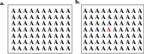
As an example of such an odd man out location, consider the example illustrated
in figures 8a,b. In figure 8a, each line contains 10 letters "A",
each of which is identical. Figure 8b is identical to figure
8a except for the single "A", which is red instead of black. This
red A immediately "jumps" out and is easily noticeable. This "A"
is referred to as an indexable location.
 |
| Figure 8. Indexable
Location. |
The Indexing operation itself consists of the following three subdivisions:
-
The properties used for indexing are computed using the information available
in the base representation. The "indexable" properties may include
color, motion, curvature, and texture in addition to others, and are computed
in parallel.
-
Using the information computed in the step above, odd man out locations
are located by comparing regions of the base representation to their surroundings
and computing a difference image.
-
Finally, processing focus is shifted to the location corresponding to the
strongest difference signal. After processing has been completed
at this location, items similar to the indexed item in close proximity
to the indexed item are processed next. Studies also indicate that
this final step may itself be further subdivided (see paper for further
details).
4.3 Coloring
Coloring refers to the same operation described earlier with respect to
the inside / outside relations and consists of marking or activating some
region surrounding a point. There are several problems associated
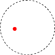
with this operation however. For example, referring to figure 9,
the small target red circle is inside the larger circle. However,
the boundary of the circle is actually a broken line and as a result, the
coloring procedure would reach infinity and it would be erroneously concluded
that the point is outside the circle.
 |
| Figure 9. Breakdown
of the Coloring Method. |
Clearly the human system is capable of correctly determining the target
is inside the circle and does not ahve the shortcomings associated with
the given the coloring algorithm. Unfortuanely, the exact coloring
process carried out by the human system is not entirely known.
4.4 Boundary Tracing and Activation
This operation allows for the tracing (following) of contours in the base
representation and is actually a useful routine employed in a variety of
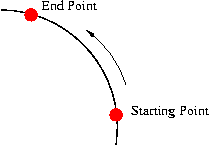
tasks. For example, as shown in
figure 10, it can be used to determine whether two points are on the
same contour. This can be accomplished as follows:
-
Start at one point and mark this point (marking is described below)
-
Trace the contour until one of the following occurs: a) The next point
is encountered - in this case, both points are on the same contour.
b) The original starting point is encountered - in this case, both points
are not on the same contour.
 |
| Figure 10. Boundary
Tracing and Activation Example. |
In a similar manner, determining whether a curve is closed or not can
also be accomplished using a similar method. This is accomplished
by starting at some point on the curve and tracing the curve.
If the original starting point is encountered then the curve is closed
otherwise it is not.
Although the tracing method appears simple, it is actually quite complex
and does require certain restrictions. For example, how are incomplete
boundaries traced or boundaries with breaks in them such as the circle
of figure 9. -how about tracing across intersections or branches - hich
branch is followed?
4.5 Marking
Allows for keeping track ("remembering") locations already processed thereby
permitting routines to shift between locations without having return and
re-process previous locations again. Marking may be used determine
whether some curve is closed - mark the starting point, trace the curve.
If the marked point is encountered, curve is closed otherwise if tracing
continues to "infinity" curve is not closed.


