Appendix A - LRF Operation
Power
The LRF is powered by an external 12V battery source. A fully charged
battery will provide approximately 16 hours of operation and requires 18-24
hours to become fully re-charged. The LRF warns the user of a low battery
by using a '*' instead of the decimal point when giving a reading.
For example, a distance of 2.43 will be given as 2*43. I have found
that about 2 hours of battery life remain upon receiving the initial '*'.
After this warning period, the LRF will no longer obtain readings and will
issue an error message (ERROR 1b). On several occasions, the 'battery
low' warning failed to appear prior to the error code.
Turning
the Unit ON - Obtaining a Range Measurement
Upon turning the unit ON, the LASER ON LED (see figure A2 below) will light
and a brief self-test routine will be conducted. If the self test
reveals a problem with the unit then an error message appears on
the display. The only error code encountered was 'ERROR 1b' which
indicates that the battery requires charging. If the self-test is
passed, the LASER ON LED goes off and 'READY' appears on the display until
measurements begin. Measurements can be initiated in one of two ways:
1. Manually:
By pressing the START button to obtain a single measurement (Single
update mode) or can be set to take continuous readings (Continuous update
mode) by installing the DATA IN adapter plug. Plugging in the adapter
plug prior to turning the unit ON results in readings being
taken immediately following power ON without pressing the START button.
2. Computer:
A computer generated "start" pulse signal (any positive going pulse)
can be sent to the LRF by a remote computer to initiate a reading (Single
update mode). Continuous update mode can also be achieved by sending
the appropriate command (see table A2 for a list of the available commands).
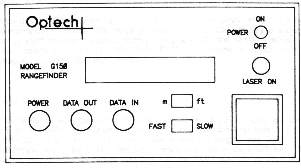 Figure A2
Model G-150 Laser Range Finder Control Panel.
Reprinted from the G-150 owner's manual.
Figure A2
Model G-150 Laser Range Finder Control Panel.
Reprinted from the G-150 owner's manual.
LRF Messages
1. Display Messages:
READY
Indicates the unit has passed its self-test and can begin taking reading.
*
Replaces the decimal point in a range reading to indicate the battery
is low
(below 9.5V). Appears on the display as well as the remote
terminal.
<
Appears to the left of the range reading indicating the over 12.5% of the
shots were
invalid (drop-outs). This is ignored in my present program
implementation.
<<<<
Appears in place of a reading (both on the display and the remote terminal)
indicating an accurate reading could not be taken.
ERROR
Appears on the display when there is a problem with the unit..
2. Beeper
-
1 SHORT BEEP Normal reading
obtained.
-
2 SHORT BEEPS Valid reading however,
more than 12.5% shots were drop outs. .
A '<' also appears on the display.
-
1 LONG BEEP
Unable to take an accurate reading. '<<<<' also appears.
Remote Terminal
Connection
The LRF is capable of asynchronous serial data communications (RS-232),
through the connection of the DATA OUT cable (containing a D9S female connector)
to a remote computer. Apple computers including the Power PC contain
an eight (min-DIN-8) pin RS-422 female connector. As a result,
to connect the LRF to the Apple, a min-DIN-8 RS-422 to RS-232 adapter cable
is required.
Several of the solder connections on the D9S became loose and were re-soldered.
To avoid any wiring mix-up, table A1 below shows the correspondence between
colour wire coming from the six pin circular connection and the pin number
of the D9S connector
|
PIN NUMBER
|
WIRE COLOR
|
|
2
|
Green
|
|
3
|
Brown
|
|
5
|
Black
|
|
9
|
Red
|
Table A1
DATA OUT to D9S Connector
Both the POWER and the DATA OUT connectors are 'snap-lock circular
connectors'. We have experienced difficulties with both connectors.
For example, readings failed to be transferred to the computer even though
they appeared on the LRF display and occasionally the power turns ON/OFF
possibly due to loose solder connections. Since the snap-lock connectors
are permanently sealed (and therefore cannot be opened to re-solder any
loose connections), replacement power and DATA OUT cable were donated by
Optech. With the use of the new cables, we have not experienced
any problems.
Control
Commands via a Serial Connection
Upon turning the unit ON, the LRF is in its default mode (controlled by
its front panel switches) even if a serial connection with a remote terminal
exists. To override the default mode the LRF must receive a control
command. There are six control commands available in addition to
the programmable shots/reading command (see table A2).
The commands can be sent at any time and in any order however, all the
commands must contain a Carriage Return (CR) as their last character.
In order to process each command, the LRF requires a certain time delay.
According to the Optech manual, this delay should be 200usec, however,
I discovered the delay time required is about 1ms.
This does not affect the proper functioning of my program since commands
are issued once only prior to obtaining any readings.
|
DESCRIPTION
|
COMMAND LINE
|
|
BEEPER ON
|
'B'
|
|
BEEPER OFF
|
'Q'
|
|
SINGLE UPDATE
|
'S'
|
|
CONT. UPDATE
|
'C'
|
|
OUTPUT IN METRES
|
'M'
|
|
OUTPUT IN FEET
|
'F'
|
Table A2
LRF Command Codes
Each command must be followed by a Carriage Return ("\r").
A computer may send
both the command and the Carriage Return together enclosed in
quotes. (e.g. "B\r").
Description of the Serial Port Data Transmitted
All readings (including 'drop-outs') consist of nine ASCII characters.
The first is an SP and the last two are CR and LF (SP, CR and LF are ASCII
characters representing a space, line feed and carriage return respectively).
Depending on whether a reading is valid or a drop-out, the remaining characters
in between are as follows:
Valid Reading:
Three characters representing the whole portion of the reading, a character
representing an ASCII period
followed by two characters representing the decimal portion.
When the whole portion of the reading requires less than three digits,
the character(s) not used are assigned SP.
Drop Out Reading:
Four ASCII characters representing '(', followed by two SP characters.
NOTE: With a terminal connection to the LRF,
upon turning the LRF ON, the ASCII characters
representing the string 'READY' are sent to the terminal.
LRF
Specification
1. Range
-
Distance readings can range from 0.2m to 100m. For our purposes,
a range between 0.5m and 15m was used. I have also found trying to
obtain a distance reading less than 0.2m results in a drop-out (indicated
by '<<<<').
2. Accuracy
-
An accuracy of 10cm is achieved between the temperature ranges of -20oC
and 50oC.
3. Measurement Time
-
The FAST/SLOW switch sets the time taken to obtain a reading by controlling
the number of shots being averaged (each distance reading is an average
of all the shots fired in order to reduce random errors). Table A3
below illustrates the relationship between the number of readings per second
and the shots per reading.
-
Two readings/second are obtained in the SLOW setting, while eight readings/second
in the FAST setting. With a serial connection many more shots/reading
settings are permitted.
-
With a serial connection, during power ON the unit will respond to the
SLOW/FAST setting, however, this can be changed by sending the desired
shots/reading at any time. Valid settings can range from 1-9999
and must be followed by a Carriage Return ("\r"). For example, for
a setting of 150 shots/reading, "150\r" should be sent.
-
Decreasing the number of shots/reading decreases the time to obtain a reading,
however, it also reduces the accuracy of the distance readings.
|
Shots per Reading
|
Average Time Between Readings (microseconds)
|
Readings per Second
|
|
1
|
69,628
|
14.4
|
|
5
|
86,760
|
11.5
|
|
10
|
111,423
|
9.0
|
|
13
|
124,306
|
8.0
|
|
20
|
154,358
|
6.48
|
|
30
|
197,384
|
5.07
|
|
40
|
240,356
|
4.16
|
Table A3
Relationship between the number of readings per second
and the number of shots per reading.
NOTE:
It has been observed that the relationship between the shots per reading
and the number of readings per second provided with the LRF operating manual
is erroneous. According to the manual, the SLOW setting of two readings
per second corresponds to 1000 shots per reading while the FAST setting
of four readings per second corresponds to 150 shots per reading.
This is clearly not the case. With a shots per reading setting of
1000, a reading was obtained approximately every five seconds (easily timed
using a stop watch) while a setting of 150 resulted in a reading approximately
every two seconds. In order to determine the correct settings, experiments
were conducted where a number of readings were obtained (50 readings) at
a particular shots per reading setting. The time between consecutive
readings (in microseconds) was measured and an average was determined.
From this average the number of readings per second was derived.
Table 2.3 above illustrates the results of several such experiments.
Although the readings per second values are an approximation, they are
accurate enough for our purposes.
4. Environmental Conditions
-
The LRF was used primarily during the day although I have experimented
with it during the night with a minimum amount of available light and have
found it works fine.
-
I have not had the chance to use the LRF during a snowfall or rainfall
although according to the owner's manual, it should work fine.
-
Windows pose a problem with object recognition since the LRF will not measure
the distance to a window. Windows do not reflect the signal instead the
signal passes through the window and a measurement of an object beyond
the window is taken.
Further information regarding the Laser Range Finder can be found in the
following available documents:
-
"Model G150 Range finder User Manual" Version 1.1, May 1991
-
"Model G150 Release Notes" June 11 1992
For parts/service regarding the LRF:
Optech Systems
701 Petrolia Road
North York, Ontario
M3J 2N6
Tel: (416)661 - 5904
Fax: (416)661 - 4168